
Cloth-Covered Clamshell Box
Treatment Criteria
This enclosure is sturdy and nice looking so it is often used for special materials.
Tools Needed
MEASUREpHASE
Board Shear
Utility Knife
Scissors
Ruler or Straight Edge
Angle (45 degrees)
Bone Folder
Glue Brushes
Weights
Materials Needed
Binder’s Board
PVA
PVA Mixture
Book Cloth
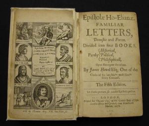 |
Our example is a volume from 1678. |
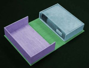 |
The box consists of three parts, all made of binder’s board, and given in order of their construction. The two color-coded illustrations show the three parts as they appear when the enclosure is opened and closed:
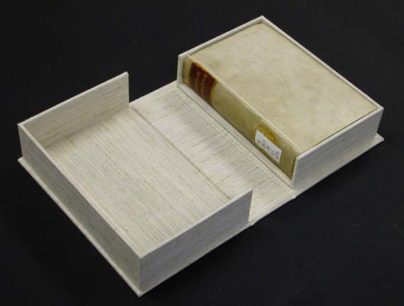
A tray (blue tinting): As can be seen in this illustration of the open enclosure, the A tray is a box in which the book fits snugly. B tray (purple tinting): This is a box into which the A tray fits snugly. It closes over the A tray, which contains the book. It is identical to the A tray in every respect except its dimensions (see terminology, orientation for A tray). C tray or “case” (green tinting): This is a flat piece the A and B trays are affixed to. Its function is similar to that of the case of a book. It is made in three sections, which compare to the front and back boards and spine of a hard spine book. The C tray isn’t really a tray; it is flat, so it may be referred to as either the “C tray” or the “case” of the box. |
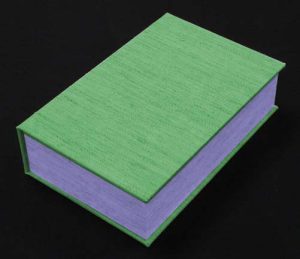 |
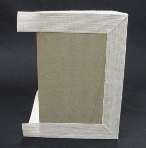
This illustration shows that both the book and the A tray are totally protected and hidden from view when the enclosure is closed. |
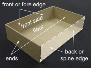 |
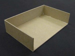
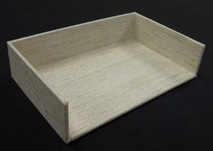
The A tray has three sides and a bottom. It is open on top and at its spine edge. Here are the terms that will be used to refer to its parts:
The bottom will be referred to as the floor. The box is enclosed at its fore edge by the piece that will be referred to as the front side. The short sides of the box are enclosed by pieces that will be referred to as the ends. |
 |
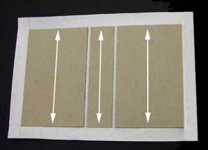
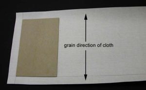
This illustration shows the orientation of grain direction of the board for the A and B trays. |
 |
This illustration shows the orientation of grain direction of the board for the A and B trays. |
 |
This illustration shows the orientation of grain direction for the C tray. |
 |
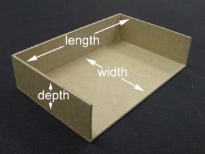
This illustration shows the dimensional terms used for the C tray. |
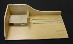 |
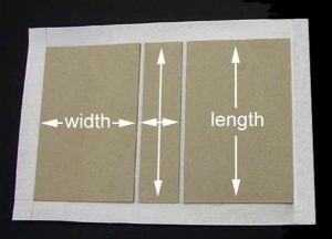
Work begins by measuring the book to be housed. This is done in the MEASUREpHASE. First the length is measured, |
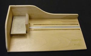 |
then the width, |
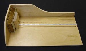 |
and then the depth or thickness. |
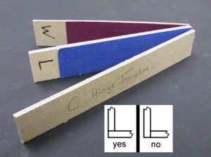 |
Because the walls of the box sit on the floor, as opposed to outside the floor (see inset), adjustments must be made to the measurements of the box’s floor, in order to arrive at the inside dimensions which will properly accommodate the book. These adjustments are made easy by the use of templates. Three templates are used in the construction of this enclosure, and with all three it is only the thickness measurement that we use. The other measurements of all three templates are arbitrary.
Specifically, the length and width templates add predetermined measurements to the length and width of the floor piece of the box. As to how much each adds: * The length template adds 2 thicknesses of board and 4 thicknesses of cloth. * The width template adds 1 thickness of board and 3 thicknesses of cloth. (The term “board”, as used here, refers to binders board of the same gauge as that from which the box is being built.) The hinge template is simply a spacer for easily and consistently determining the distance between the three sections of the C Tray or case. It is composed from two thicknesses of board for a single-wall box like the one being built in these instructions, and three thicknesses of board for a double-wall box. (This will be pointed out again later, in the C tray instructions.) All templates are illustrated in action, as they are called for. |
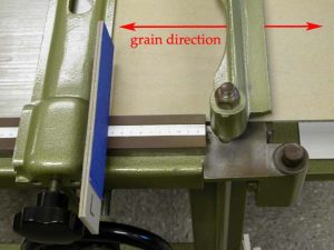 |
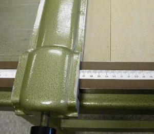
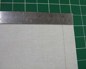
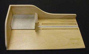
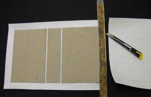
We now move to the board shear. The pieces of the A tray are made first, beginning with the floor piece. It is first cut to length, so right off the bat we need the length template. This illustration shows how the length template is used. It is placed against the fence of the board shear in order to add the thickness of the template to the length measurement of the box’s floor piece. The fence is set so that the right-hand side of the template is at the length dimension of the book on the ruler, and the piece is cut.
It should be noted that the ruler of the board shear reads right-to-left. |
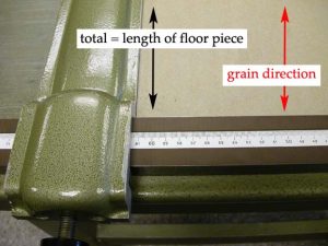 |
We now have a piece of board whose shorter dimension equals the length of the A tray’s floor piece. Ideally, the piece’s longer dimension is sufficient to yield:
* the width of the floor piece, plus It is efficient to cut these pieces from the same piece of board, provided it is long enough. If not, it is wise to cut another piece of board to the length measurement of the floor now, before the fence is moved. But we will assume that our board is long enough for both pieces. The piece of board is turned 90 degrees from its orientation in the previous step, then: 1. The front wall and end walls will be cut to depth, 2. The floor will be cut to width, and 3. The end walls will be cut to length. The depth of the front and end walls is 4.0 cm in our example. Cutting pieces this narrow using our board shear presents problems if one attempts to use the fences. The fence ruler only goes down to about 8 cm. One could use the outside fence, but the one on our shear is cumbersome and not all that accurate, for which reason we scarcely use it. Fortunately, there is a way to cut narrow pieces easily and accurately. First, the board is situated so that it just overhangs the cutting edge of the shear on the right. The fence is nudged up to the board on the left and locked at the nearest measurement on the fence ruler that will make it easy to subtract the depth measurement, and the board is cut. In our example, the depth measurement is 4.0 cm, which will be easy to subtract from any number because it ends with “.0”. But of course this is not always the case. If, for instance, the depth measurement was 4.6 cm, we would stop the fence at the largest measurement that (a.) ends with “.6” and (b.) leaves a bit of board overhanging the cutting edge. Let’s say that measurement was 58.6 cm. The board would be cut, the fence would be moved to 54.0 (58.6 minus 4.6), and the board would be cut again, yielding a piece 4.6 cm in width. In our example, the fence is stopped at 61.5 cm, and the board is cut. |
 |
The first setting being 61.5 cm and the depth of the front wall being 4.0 cm, we now move the fence to a setting of 57.5 cm (61.5 cm minus 4.0 cm.) The board is cut, yielding a piece 4.0 cm in width and the same length as the floor, which are the dimensions the front wall piece needs to be. |
 |
Leaving the fence locked, the 4.0 cm front wall piece we just cut is placed between the fence and the piece of board we just cut it from. The board is cut, yielding a second piece (an end wall) 4.0 cm in width. This piece is likewise placed between the board and the fence, i.e., in addition to the first one, and a third 4.0 cm piece (the other end wall) is cut.
The other (longer) dimension of the end wall pieces will be a bit excessive, which is fine. We will set them aside for a moment and cut the floor piece to width. |
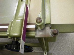 |
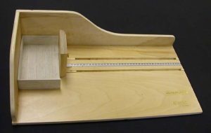
Here we see the width template in action, and we see that it is used in exactly the same manner as was the length template. The floor piece is cut to width and is finished. |
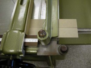 |
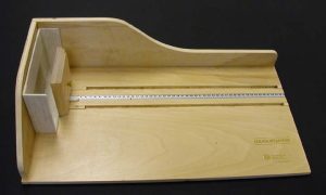
Do not move the fence.
The two end wall pieces are now cut to length. The walls sit on the top surface of the floor, and the front wall runs the full length of the floor. This means that the end walls can not run the full front-to-back width of the floor. Rather, they must fit inside the front wall and butt up to it. So, a downward adjustment equaling one thickness of board must be made. The length measurement of the end pieces thus equals: * the width of the floor minus one board thickness So far, we have used templates to add to measurements. We will now use a template (in this case, simply a piece of board) to subtract from a measurement. As of the previous step, the fence is already set to the width of the floor. A piece of board is placed on edge between the end wall pieces and the fence, as shown. This will yield pieces whose length is [the fence setting] minus one board thickness. In our case, this is [the width of the floor] minus one board thickness. As you can see above, this is correct. The end pieces are cut to length. Review: using templates Make sure you understand how templates work to add to and subtract from measurements. In both cases, the template is placed against the right hand edge of the board shear’s fence. * If you are adding to a measurement, the appropriate template is placed on the ruler of the shear. The effect is that this moves the fence (and thus any pieces you are cutting) to the left, or away from the cutting edge, making them longer. * If you are subtracting from a measurement, the appropriate template is placed on the table of the shear. This moves the fence/pieces to the right, or nearer to the cutting edge, making them shorter. The orientation terms “left” and “right” are of course in accord with the view given in the illustrations. |
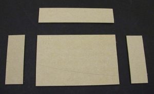 |
All of the pieces of board for our A tray are now complete, as shown in this illustration. |
 |
The pieces are now assembled. The adhesive used is straight PVA. First, adhesive is applied to one long edge of the front side piece and it is glued to the floor, with which it is made flush at the ends and all along the front edge. Then adhesive is applied to one long edge and one short edge of each of the end pieces. The long edge joins the floor, the short edge joins the front side. They should be flush with the floor at its ends and back edge. The structural work of the A tray is now complete. |
 |
The A tray is now inverted and placed under weights. PVA sets far more quickly than mixture. In the case of this particular structure, covering can begin in as little as 5 or 10 minutes with only minimal care in regard to handling. And it seems that full bond strength is attained within somewhat less than an hour’s time under normal drying conditions. |
 |
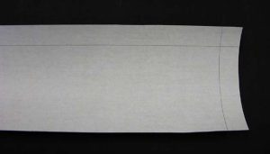
We are now ready to begin covering the A tray with book cloth. We will be using Canapetta. The first piece of cloth will cover the ends and the front side of the tray. This will require a long, narrow piece of cloth, and the grain of the cloth will run the short way of the piece, or grain short.
The long dimension of the piece of cloth needs to be at least equal to: * two times the width of the tray, plus the length of the tray, plus 5 cm., or: Long dimension = (2W + L + 5 cm) This piece will cover the three walled sides of the tray (the front side and the ends), with a 2.5 cm turn-in at both ends. Again, this is the minimum; excessive is fine. Quite often, the beginning long measurement of this piece of cloth is the width of the bolt (roll) it is cut from (minus the selvage). The short dimension of the cloth is figured by a formula: The depth measurement of the front side/ends, times 2, plus 5.5 cm, or: Short dimension = 2D + 5.5 cm The 5.5 cm allowance provides for a 2.5 cm turn-in on the top and bottom sides of the floor, plus it accounts for the thickness of the front side/ends and the thickness of the floor. We know the depth measurement to be 4.0 cm., so the short measurement of the cloth would be (4.0 cm x 2) + 5.5 cm = 13.5 cm. |
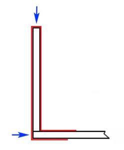 |
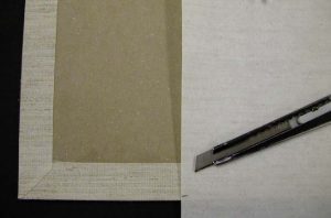
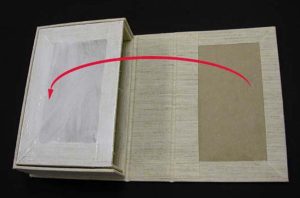
Here is a drawing that may prove helpful in visualizing what these measurements mean, before we see the actual process of covering. The cloth is represented by the red lines. The blue arrows point out the two thicknesses of board the cloth must cross, which account for the .5 cm beyond the 5cm for the two turn-ins. |
 |
It is helpful to mark the cloth with two guidelines, both 2.5 cm in from the edge of the cloth. These marks will allow for a 2.5 cm turn-in at each of the edges. One will be at the end where covering will begin, the other at what will be the bottom of the tray. Though this latter mark is at what appears to be the top in the photo, the orientation will hopefully make sense beginning with the next image. |
 |
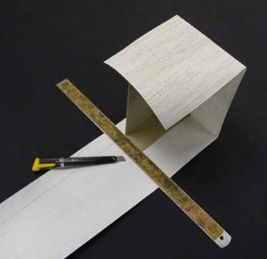
One end of the tray is covered with PVA mixture, and the tray is aligned with both the marks on the cloth. It is important that the edge of the cloth with the lengthwise mark be at the bottom of the tray, not at the top. As you can see, the excess at the top is far greater than 2.5 cm, and we will need all of it. (Remember, the short measurement of the cloth is at its final dimension.) |
 |
Now the front side of the tray is covered with mixture, and the tray is “rolled on around,” maintaining alignment with the lengthwise mark. If necessary, the cloth should be worked snugly in the direction of the end yet to be covered, in order to avoid wrinkling due to excess at the corner that has just been covered. |
 |
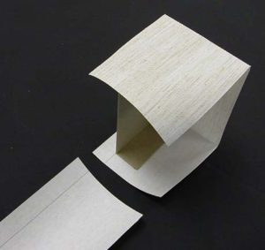
The last end is covered by the same method given above. |
 |
The cloth is trimmed off width 2.5 cm. left. |
 |
… leaving a 2.5 cm turn-in. |
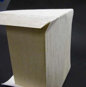 |
Next, the turn-ins on the bottom of the tray are dealt with. The cloth is gathered at the two corners as shown … |
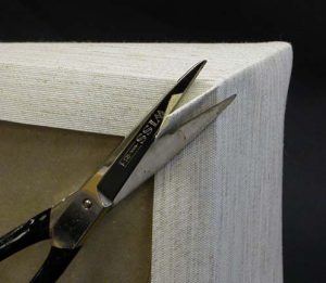 |
… and the excess is trimmed off as closely as possible with scissors. |
 |
The result should look something like this. |
 |
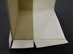
The turn-ins are now glued down, beginning with the one at the front edge. |
 |
The turn-ins at the ends follow and slightly overlap the one at the front edge. All are smoothed down with a bone folder. |
 |
The top view of the tray should now look like this. |
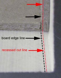 |
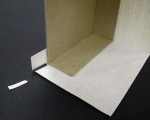
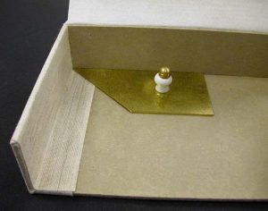
Some of the cuts we will be making in the next few steps are recessed cuts. This illustration serves to help define this term as it will be specifically used. What it means is that the cloth is not cut right on the board edge line, but rather just off of it, in the direction that will yield a tiny bit of excess in the corner when it is folded into place. There is no established measurement for the amount of recess, but it lies somewhere around .5 mm. |
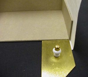 |
This will be our first recessed cut. Here we are positioning the brass angle (of the type we call the “brass Nevada”). The angle serves as both a square and a straight edge. This is the same corner shown in the last image (the close-up). So, the direction of the recess for this cut would be just to the right of alignment with the vertical board’s inner edge. |
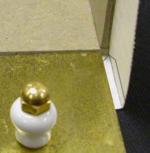 |
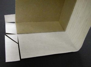
Here is a close-up of all the cuts we will be making at this corner. The two short cuts are at approximately 45 degrees. The other long cut will also be a recessed cut. As shown in this image, the direction of its recess would be down. In fact, it will be about in line with the top surface of the brass angle. |
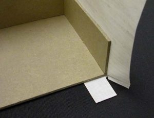 |
One side is cut. |
 |
And now the other side is cut, yielding a scrap roughly the shape of the Washington Monument (as once noted by former student conservation technician Rachel Lapkin). |
 |
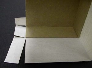
Now we move to the corner at the top of the tray. We begin by making two recessed cuts. As a point of bearings, the direction of the recess of the cut that is open to a V shape would be to the left of the board edge. Incidentally, this cut appears V-shaped because the flap of cloth on the right has been shifted over slightly for the sake of illustration, not because a V-shaped cut was made. |
 |
The view of the same corner after turning the tray clockwise 90 degrees. Again, the cut in the foreground has been opened to the V shape, again for the sake of illustration. The direction of the recess of this cut would be to the right of the board edge. |
 |
The center tab of cloth is now trimmed at approximately 45 degrees and about 2.5 cm from the corner of the board. |
 |
Here is the tray with all the corners cut. |
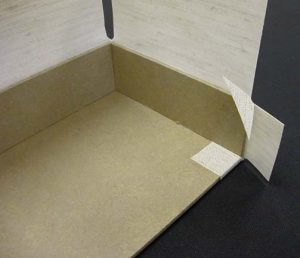 |
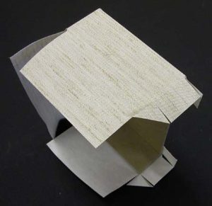
Now we begin to glue down the cloth. In the case of all the flaps we will be gluing down, the adhesive is PVA mixture, applied to the flaps of cloth, not to the board. We begin with the turn-in at the bottom of the tray’s back edge. It will be glued to the floor and worked down with a bone folder. The excess created by the recessed cut will be in the corner formed by the junction of the floor and the end. |
 |
Next comes the triangular piece at the top of the tray’s back edge. It is centered so that equal amounts of cloth lap over onto each of the end piece’s edges. |
 |
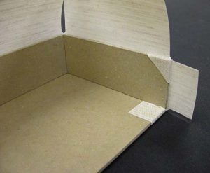
Then the cloth at the back end of the end piece is affixed. |
 |
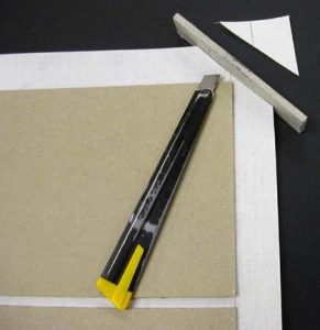
The front edge of the turn-in is trimmed to a 45 degree angle using a razor knife guided by a brass Nevada. The scrap is removed and discarded. |
 |
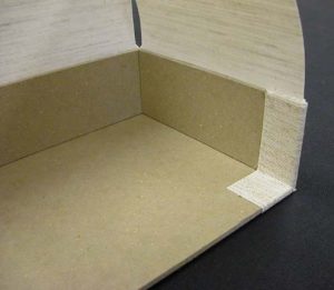
All flaps of the tray’s other end having been treated as above, we are ready to glue down the final flap, the one at the front edge. |
 |
The front flap is glued down and also trimmed to a 45 degree angle by the same method shown above. |
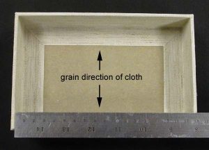 |
Measurements are now made for the piece of cloth that will cover the floor. The inside length measurement of the tray is taken, and 1 mm subtracted from it. This will be one measurement of the cloth. The other measurement will be the width of the tray plus 2.7 cm, this extra being to allow for the thickness of the floor plus a 2.5 cm turn-in on the bottom of the tray. Grain direction of the cloth is as shown. |
 |
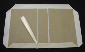
The cloth is glued up and put into place. Again, the adhesive is applied to the cloth, not the floor of the tray. The cloth is situated into place and worked down with a bone folder. The A tray is now finished. |
 |
Everything we have done so far to bring the A tray to completion is now repeated for the B tray. But the B tray must contain the A tray, so naturally it must be larger. So instead of measuring the book, we simply measure the A tray, beginning with its length, |
 |
then its width, |
 |
and its depth. |
 |
All the steps for constructing the A tray are repeated, using the larger measurements, and the B tray is now finished. |
 |
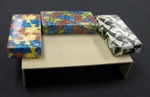
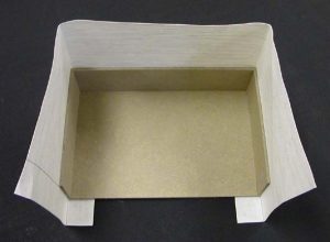
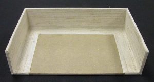
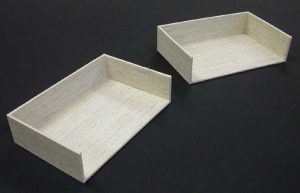
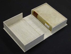
Here we see the top view of the two trays, showing their proportionate sizes. |
 |
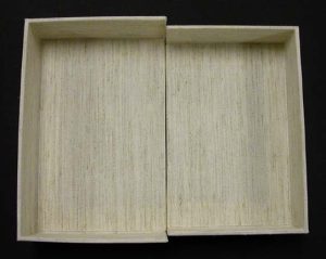
And here we see the two as they nest together. |
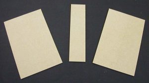 |
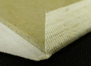
Next, the pieces of board for the C tray or case are cut. The measurements of the two larger pieces (the “boards”) are:
* the length of the B tray plus 6 mm, by * the width of the B tray plus 3 mm The measurements of the spine piece are: * the length of the B tray plus 6 mm, by * the depth of the B tray It is best to make this latter (depth) measurement with the A tray in position inside the B tray (as seen in the previous slide). If the bottom (floor) side of the A tray protrudes at all above the ends of the B tray, the measurement will be too small if the B tray alone is measured. If this happens, the box will not fully close and the C tray will have to be made over. This measurement is best made in the MEASUREpHASE. |
 |
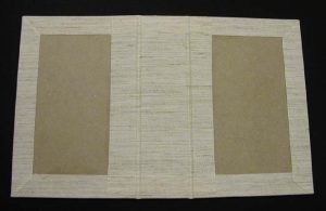
The cloth that will cover the case is now cut. Its dimensions are:
* the length of the case’s length measurement plus 5 cm, by * at least the combined width of the three case pieces plus 7 cm. (This is the minimum; excessive is fine.) Marks are made 2.5 cm from two adjacent edges of the cloth and assembly begins by gluing up one of the wider pieces and aligning it with these marks. The adhesive, PVA mixture, is applied to the board, not the cloth. Grain direction of the cloth is as shown. |
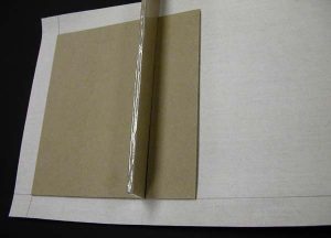 |
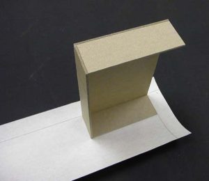
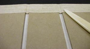
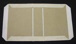
The spine piece is glued up, and the hinge template is now called into action. Again, it is two boards thick. As the illustration shows, it is simply a spacer for easily and consistently determining the size of the space between the pieces of the case.
Note: I realized that this illustration could be confusing, since on first glance it looks a little like the top edge of the template has been glued with PVA. In reality, the white areas are just gloss from the clear plastic tape in which the template has been wrapped to increase its resistance to adhesion, as well as its lifespan. |
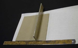 |
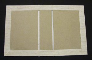
The bottom edges of the two pieces of board are aligned against a straight edge. |
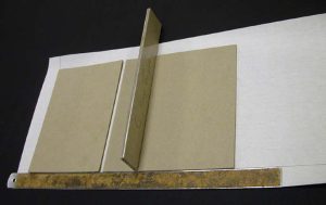 |
The third and final piece of board is glued up and positioned as per the methods given above. |
 |
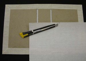
The excess cloth at the end is trimmed down to a 2.5 cm turn-in. |
 |
The four corners of the cloth are cut at roughly a 45 degree angle across. Again, a simple spacer-type template is used. The template is composed of two thicknesses of board, so the four cuts are spaced two board thicknesses outward from each outer corner of the board. The C tray hinge template can serve as the spacer. |
 |
Next comes gluing down the turn-ins. The top and bottom are first, followed by the ends. The cloth is deliberately gathered slightly inward as it is laid down. This creates a bit of excess in the center, which is put to good use in going around all the steps created by the board edges. The cloth is worked into these recesses with a bone folder. The adhesive used is PVA mixture and as with all turn-ins the adhesive is applied to the cloth, not to the board. |
 |
Here the process of forming the cloth around the boards has begun. |
 |
Now the cloth at the corners is simply worked down over the board edge and flattened onto the workbench, again using a bone folder. |
 |
The turn-ins at the ends will be glued down next. They get no special treatment at the corners; they only need to be folded over and smoothed down with the bone folder. |
 |
The exterior covering of the case is now completed, and the view from the interior looks like this. |
 |
The piece of cloth that will cover the interior of the spine is now cut. First, its width. This measurement is not critical; it just needs to lap about 2.5 cm over onto the “boards” of the case as shown. After making all the corners at the hinges, a bit less will actually end up lapping over onto the boards, and that is fine. |
 |
The length measurement of this piece of cloth is that of the case minus 1 mm. |
 |
The cloth is glued up and put into place. The cloth is worked rigorously into the hinge recesses using a bone folder. The case is now finished and we are ready for final assembly. |
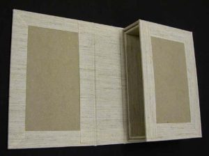 |
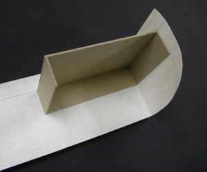
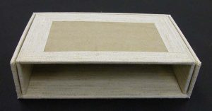
This illustration shows how our components will go together to make a clamshell box. With the C tray or case laid out flat, we see the A tray nested inside the B tray. Both will be affixed to the case. |
 |
The bottom of the B tray is glued up and it is positioned on one of the boards of the case so that it is bordered on three sides by equal amounts (about 3 mm) of square. The case is then closed over the B tray. |
 |
The bottom of the A tray is now glued up and then placed into position inside the B tray. The case is closed over both. |
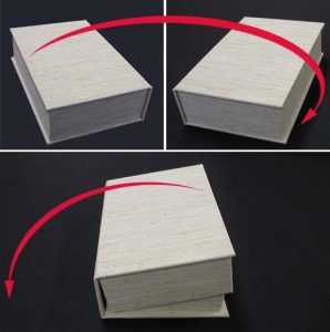 |
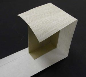
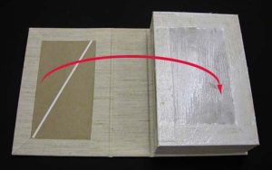
The case now needs to be opened back up and laid out flat, in order to place the box under weights in the open position. However, there is a risk of the A tray shifting out of position if the box is merely opened back up from its current position. If the A tray shifts and this isn’t noticed, the A and B trays obviously won’t fit together. And if the glue sets with the A tray out of alignment, the box is usually ruined. Sometimes it can be disassembled and done over, but the results are never as good as those yielded by getting it right the first time.
A trick for making the opening of the case less worrisome is shown in the two images at the top. Simply flip the entire box upside-down. As can be seen in the image at the bottom, this puts the freshly glued A tray on the bottom, rather than hanging from the case by wet glue, and this naturally reduces the chances of misalignment. The B tray is considerably less likely than the A tray to shift out of position, as by now its adhesive will have bonded and begun to set. |
 |
The box is now opened out flat and placed under weights to dry, usually overnight. The only thing remaining to be done is to attach any labeling, such as a title label for the spine, barcode, call number label, etc. |
 |
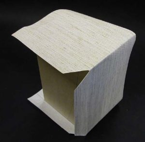
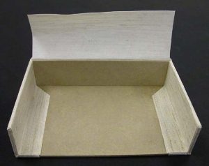
Here is the completed box in open position, |
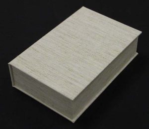 |
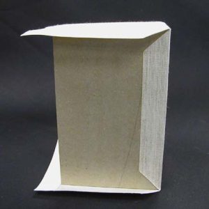
and here it is shown closed. |