
Phase Box
Treatment Criteria
Phase boxes are constructed from two pieces of gray/white board. The box is of a 4-flap design that lays out flat on a table when opened, in which state it assumes the shape of a cross. Thus, the two pieces are called simply the vertical piece and the horizontal piece.
Tools Needed
Board Shear
Crimper
MEASUREpHASE
Ruler
Hammer/punch
Rivet Bucker
Tweezers
Materials Needed
Gray/white board
Rivets/washers
Waxed thread
PVA
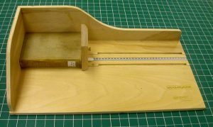 |
First, the book is measured, using the MEASUREpHASE: length, |
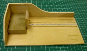 |
width, |
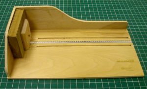 |
and thickness. |
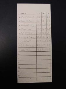 |
The measurements are recorded onto a sheet such as the one shown. |
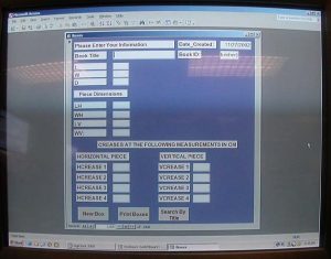 |
Overall dimensions of the two pieces (vertical and horizontal) are determined, as well as the location of the creases. Our lab uses a computer program for this; the dimensions of the book are entered, and the program calculates all the necessary measurements. However, instructions, along with drawings, are given here for calculating all these measurements manually, working from the dimensions of the book. Another method for marking the location of the creases does not involve measuring – instead the book can be laid down on the strip of board and the position of each crease is marked. In this method, one crease is marked then made. Then the next crease is marked and made, and so on.
For our example, we will say the book measures: 24.0 cm long, 12.0 cm wide, and 6.0 cm thick. L, W, and D refer to the length, width, and depth (thickness) measurements of the book, so: L = 24.0 cm W = 12.0 cm D = 6.0 cm |
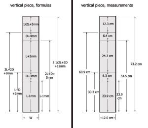 |
First, the vertical piece:
Formulas, vertical piece: The width of the vertical piece = W. The location of the first crease is at: L – 1 mm. In actual numbers/measurements): The width of the vertical piece = 12.0 cm The length of the vertical piece = 73.2 cm The location of the first crease is at: 23.9 cm. |
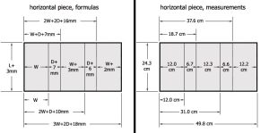 |
Now the horizontal piece:
Formulas, horizontal piece: The width of the horizontal piece = L + 3 mm. The location of the first crease is at: W. In actual numbers/measurements: The width of the horizontal piece = 24.3 cm The length of the horizontal piece = 49.8 cm The location of the first crease is at: 12.0 cm. |
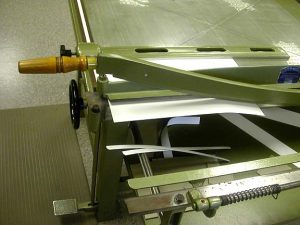 |
We are now ready to make the horizontal and vertical pieces from grey/white board.
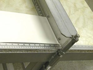
Grain direction for both pieces is grain short. This puts the grain running parallel to the blade of the crimper, which we will be using to make the creases. The cut marks for the pieces are made on the board and each piece is marked with the following information: * its line number from the measurements sheet, and * “H” or “V”, to denote whether it is the horizontal or vertical piece The horizontal and vertical pieces are cut to their overall dimensions, using the board shear. |
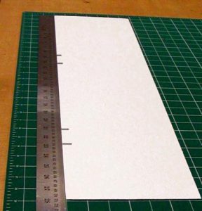 |
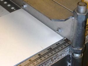
The locations of the creases are now marked onto the pieces. |
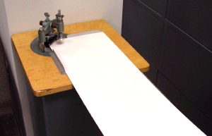 |
The corners of both pieces are rounded, using the corner rounder. |
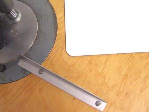 |
Here is shown the radius cut by the corner rounder. |
 |
The blade of the crimper is aligned with each mark … |
 |
… and the crease is made. |
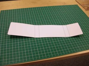 |
This image shows the vertical piece with its four creases. The same procedure is followed for the horizontal piece. |
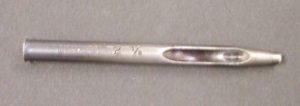 |
Next, two holes are punched in what will be the right hand edge of the horizontal piece. These are to accommodate the rivets. Here is the type of punch used, one with a hollow, tapered end. The cutaway in the side allows for removal of the scrap plugs that accumulate inside the punch. It punches the holes by means of striking it with a hammer, and this is done on a designated “punch pad”, which is a pad made of about 8 or 10 thicknesses of binder’s board. |
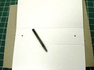 |
The holes are centered between the two creases of the edge and located about 1″ in from each end. |
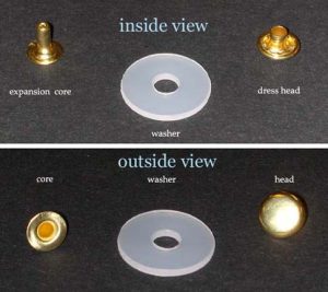 |
Here are the views from both ends of the rivets used for closures, showing the two components, the expansion core and the dress head. Also pictured is the neoprene washer. |
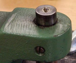 |
This is the mandrel of the rivet bucker. The flared end of the rivet’s core fits onto the conical pin in the center. |
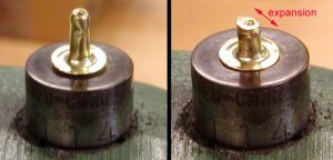 |
The core is smaller in diameter than the dress head and thus fits inside it. Here is an exposed view of the expansion core, without the dress head, before and after bucking, showing that it expands inside the dress head and locks the two halves of the rivet together. |
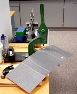 |
The hole in the washer is aligned with the hole in the board, on the gray side. The core is pushed through the hole from the white side, so that it protrudes through the board and the washer on the gray side. The dress head is snapped onto the core, the flared end of the core is positioned on the conical pin of the mandrel, and the rivet is ready to buck. |
 |
The lever of the rivet bucker is simply pulled down. This lowers the plunger, which is concave to mate with the convex curve of the dress head. When the downward force is exerted, the core expands inside the dress head, locking the two halves of the rivet together and securing the captive position of the washer. |
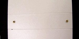 |
Here is the view after bucking, from the white side (inside) … |
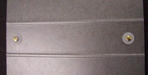 |
… and from the gray side (outside). |
 |
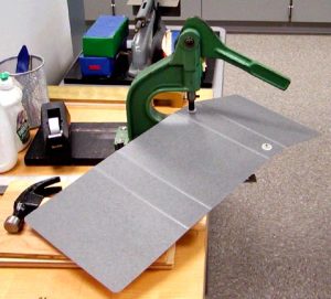
The horizontal piece is now folded as shown, in order to determine the location of the holes the ties will pass through. The ties are made from pieces of waxed thread. |
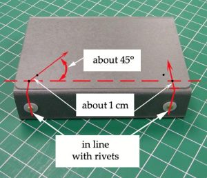 |
The holes are located as follows:
1. Directly in line with the center of each rivet and about 1 centimeter from the edge of the board. In the directions that follow, this will be called the outer hole. 2. About 1 cm from the first hole, at about a 45 degree angle inward. This will be called the inner hole. |
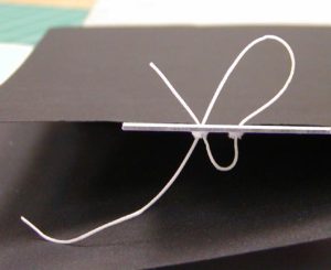 |
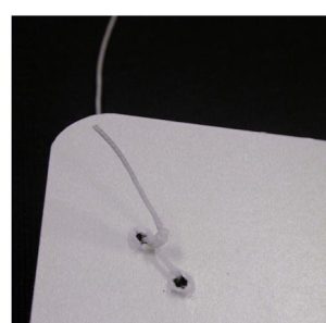
The tie is threaded up through the outer hole (on the left in the image), then down through the inner hole, then back up through the outer hole. A rather long tail is left below, as shown. Note that in this and the following illustrations, the inside (white side) of the board is facing up. |
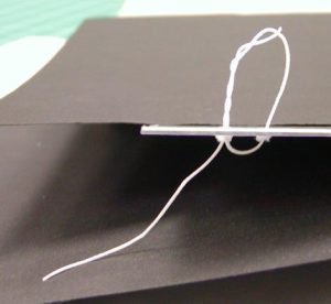 |
The loose end passing through the outer hole is wound about 3 or 4 times around the other piece of the tie passing through this hole. |
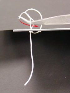 |
The two are separated down at the surface of the board, and the loose end is pulled back through. Tweezers are very handy for this, as seen in the illustration. |
 |
The entire knot is held securely to the board with one finger, and the long tail below is pulled until the knot is snug. The tie is now finished. |
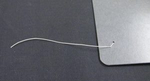 |
And here is the exterior view of the finished tie. |
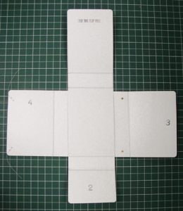 |
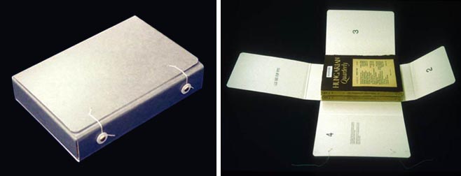
The two pieces are now ready to be glued together, following which they are weighted and left for about a day. Straight PVA is the adhesive used, as this is a board-to-board joint. The vertical piece goes on top, as shown.
The closing order is marked on the flaps. The top one reads “fold this flap first”, and the others are numbered. The order is: top, bottom, right, left. |
 |
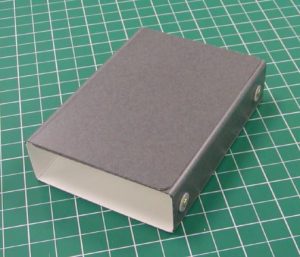
Here the finished enclosure is shown in both the open and closed states. |